Overview #
Routing is a mechanism where there is a selection of a path for traffic in a network, where a packet is analyzed in source and destination and managed by a specific packet forwarding mechanism, or the same, the management from one network interface (ingress) to another (egress).
Routing implementation can be done from different devices like switches, firewalls, servers, load balancers, really any device that is able to receive/send packets, for that, RELIANOID does an advanced routing implementation super-efficient and effective adding options to be configured as customized if required, but how a simple routing system works and how RELIANOID Routing implements it and how to use the advanced features?
Basics #
Any simple routing system includes one simple routing table, this table is responsible for checking traffic rules against the packet like where source IP is coming from the packet or where and destination IP is going the packet to. Finally if the packet doesn’t match with any condition then the simple route table will forward the packet to the gateway and the packet will continue the path.
But what happens if more advanced behavior is required? For example, how to send the packet to different gateways based on the source address, or even forward the packet coming to the same network-based in complex algorithms or based in a marking packet system, so it is here where the RELIANOID implementation is taking place working in the following way.
When a packet is received, it is checked against a rule table, this rule table is responsible for sending the packet to a different routing table based on the information in the packet, once the forwarding decision to the routing table is taken the packet is checked against the given route table and finally sent to the next hop as indicated in the routing table.
Exploring a simple routing configuration #
The following diagram explains how a simple routing system takes the decision for packet forwarding:
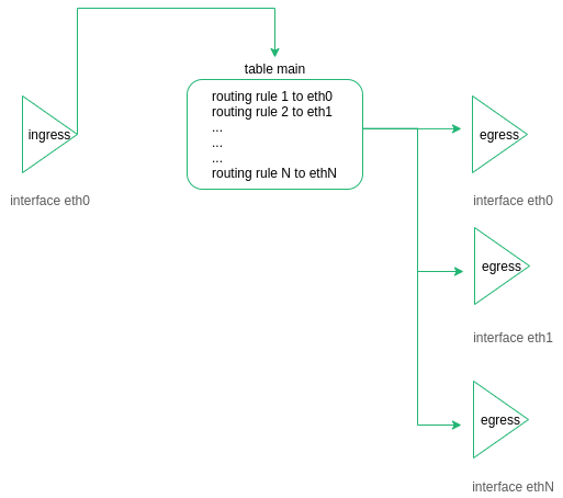
The packet ingresses in the device through eth0 and the routing table checks the packet destination, now the packet will be sent to a given interface to be egressed. This way of working is simple and useful.
Exploring an advanced routing configuration in RELIANOID ADC #
As we already indicated the RELIANOID ADC appliance includes an advanced routing system, where first the packet is “rulerized” to be decided secondly to which table forward to it:
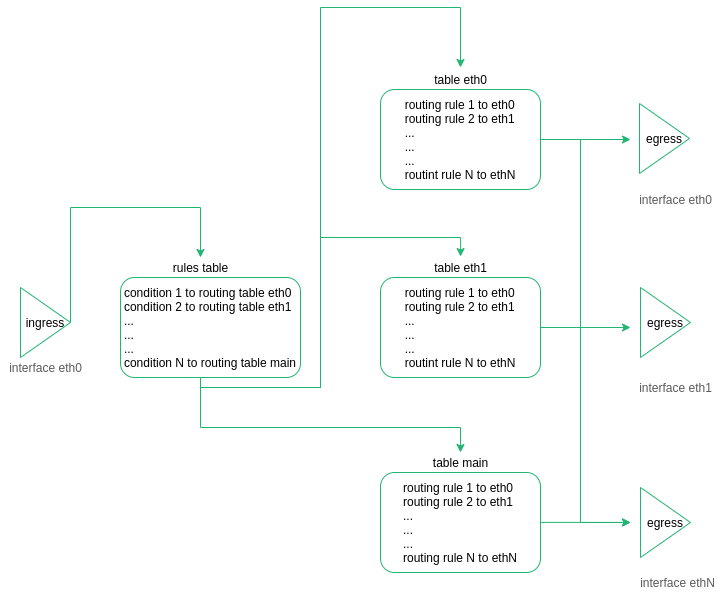
The routing module of RELIANOID ADC was designed with the following idea:
Each network interface (NICs, VLANs or Bonding) manages its own Routing table and gateway.
The traffic reaching a VIP will be managed by the same routing table for incoming traffic (from client to load balancer) than for outgoing traffic (from the load balancer to backend)
Each packet reaching a farm is marked so this mark is taken into account to redirect the packet to the next hop.
To keep a routing system simple with a minimum number of static routes because the static routes would increase adding more Interfaces.
In case that the ADC requires to connect to external systems, navigation proxy, DNS, hot fixes review, etc, a dedicated table will be used (table main).
Load Balanced traffic will use different tables than the main, to separate and isolate different kinds of traffic.
The following lines describe a real scenario, a RELIANOID ADC is configured with two NICs (eth0 and eth1).
Listing the routing table for NIC eth0:
ip route list table table_eth0
eth0 IP 192.168.100.10
eth0 NETMASK 255.255.255.0
eth0 Gateway 192.168.100.5
Listing the routing table for NIC eth1:
ip route list table table_eth1
eth1 IP 192.168.101.10
eth1 NETMASK 255.255.255.0
eth1 Gateway 192.168.101.5
VIP1 192.168.101.11
The default gateway for the table main is 192.168.100.5.
This information can be shown with the command:
ip route list table main
A client reaches a virtual IP 192.168.101.11 in a farm L4XNAT in port 80, this farm has been configured for load balancing traffic against two backend servers 192.168.200.20 and 192.168.200.21.
The L4XNAT farm inside the LSLB module (Local Service Load Balancing) gives a unique mark identifier to each backend in each farm, so as soon as a packet reaches the VIP 192.168.101.11 in the Virtual port 80 configured in the eth1 the load balancing module assigns a mark to the packet just to identify the new destination, in the following step, the rule system checks the mark in the packet, based in this mark the routing system know to which route table the packet needs to be sent.
For example, the l4xnat farm marks a packet with the value 201, which identifies the backend 192.200.20 in the farm configured in Virtual IP 192.168.200.20 and virtual port 80, now the rule table is able to forward the packet to the corresponding route table:
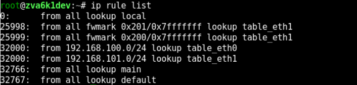
The routing rules can be listed with the command:
ip rule list
As it is shown in the ID 25998 all the traffic marked with mark 201 will be forwarded to table table_eth1, let check the content of table eth1:
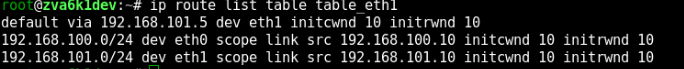
Now the packet tries to reach the backend 192.168.200.20, checking the table, this destination IP is not accessed directly, so the default gateway will be used and the packet will be forwarded to 192.168.101.5 as the next hop.
With this mechanism First the System marks packets to identify the destination and later the advanced Routing system is able to forward the packet in a proper way to confirm it will reach the correct destination.
Additionally, the Routing system can be configured and modified as client requirements, In case you want to alter the rule system please refer to the web GUI section NETWORK > Routing > Rules and in case you want to alter some routing table please refer to the web GUI section NETWORK > Routing > Tables.


